Drawings out of a plant model
IndustroML is a schema, an editor and a catalogue for describing industrial plant: the electrical and mechanical systems of a data centre as containers, assets, interfaces and connections. Until this month the only pictures it made were Mermaid diagrams. Those show what connects to what. They aren't drawings anyone would issue.
Now drawings/
turns a model into an electrical single line diagram (SLD) and a P&ID, as
DXF for CAD, PDF to issue and PNG to review.
What goes on a sheet
Each drawing sits on an ISO 5457 sheet, the smallest of A3 to A0 it fits
at full size, with a zoned border. The title block is filled from the
model's meta.drawing and the revision table from meta.revisions.
Missing fields stay blank. The legend lists only
the symbols that sheet uses, and the last note names the model file and
its SHA-256, so a print can be traced to the model that made it.
The DXF is AutoCAD 2013 format, in millimetres, drawn full size. Symbols
are blocks with attributes (TAG, RATING, VOLTS), so a value can be
edited in CAD without exploding anything, and every layer carries its own
colour, linetype and lineweight. FreeCAD's importer drops block
attributes, so --flat explodes the symbols into plain lines and text.
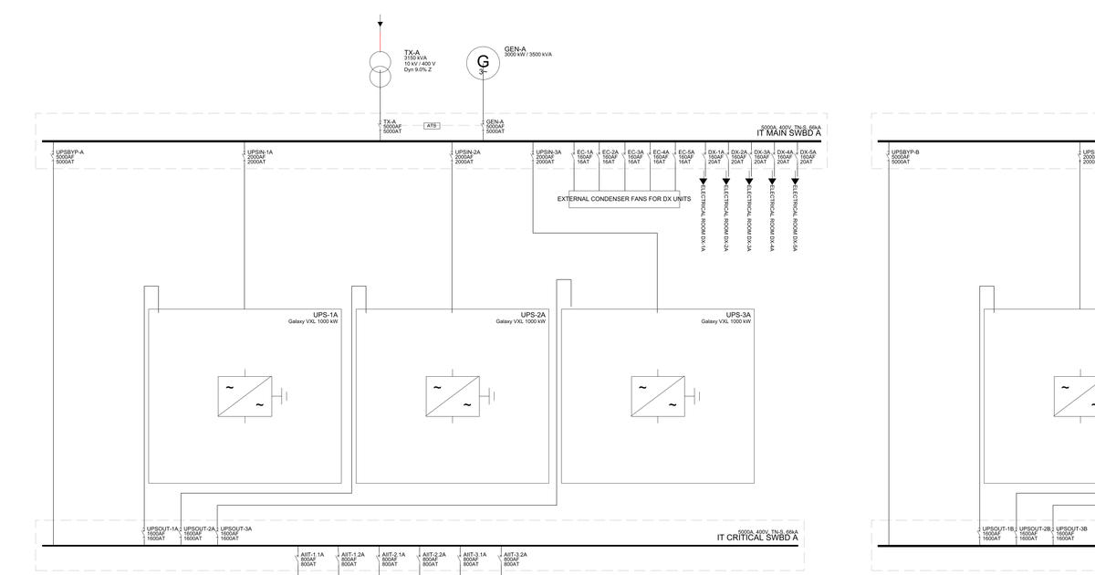
On the SLD, boards are busbars in dashed enclosures, with the protective device on each feeder taken from the port's attributes. Each cable has its construction and length written beside it, and HV is drawn in red. Symbols follow IEC 60617 (AS/NZS 1102). The P&ID lays equipment out in flow order, puts valves and strainers inline in the order the model connects them, draws instruments as ISA-5.1 bubbles, and gives each service its own layer and colour. Symbols follow ISO 10628-2.
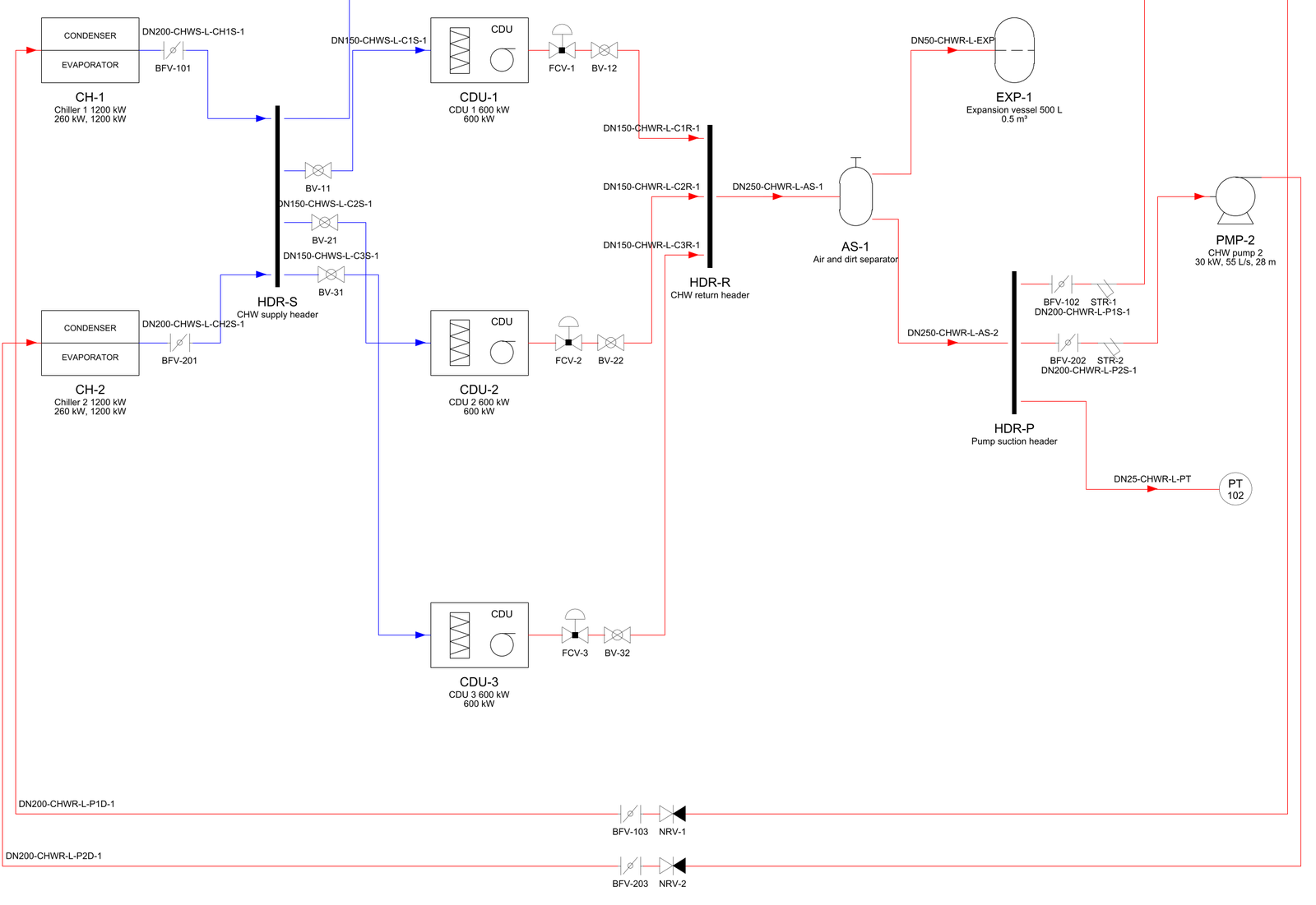
DN-service-id.Splitting over sheets
The first real project model I drew had four main boards, dual-fed cooling boards and two chilled-water loops. On one sheet it was unreadable. The SLD now splits the way a drafter would. A final board, one whose circuits all end at loads, gets its own sheet, and its supplies arrive at off-sheet connectors that name their sheet ("FROM MSB-A F-MECH, SHEET 1"). Everything above goes on an overall sheet. If that overall sheet would still print below 0.6 scale, each main board gets a sheet of its own too. The P&ID draws separate loops in their own bands, and gives each loop its own sheet when the combined one would be too small.
--sheet A3 issues every sheet at one size, scaled to fit, because a set
issued at A3 is what people print.
Drawn where the model says
Automatic layout suits a model of tens of items. I tested it by reading a
full reference-design P&ID (about 950 pipes, 350 valves, 330 tees) into a
model and drawing it back, and the automatic layout turned that into
spaghetti. So the schema gained optional positions: an asset can carry
schematic: {at, size, rotation} and a connection a schematic.path.
When every asset on a pipe is placed, the P&ID isn't laid out at all:
assets:
- id: NRV-1
  kind: valve
  attributes: {valve_type: check}
  schematic: {at: [12.0, 40.0], rotation: 0}
connections:
- id: L-101
  type: pipe
  from: PMP-1.DISCHARGE
  to: NRV-1.IN
  attributes: {service: CHWS}
  schematic: {path: [[13.5, 40.0], [12.0, 40.0]]}
The read-back also showed what the schema couldn't hold. Tees and
flexible connections became asset kinds, and interfaces gained a role
(supply, return, suction, discharge and so on). A pipe with dn_mm is now
labelled with its size beside its longest run, but
only if that run is long enough to carry the text.
Reading RD110 back in
Schneider Electric publishes Reference Design 110, a 10 MW GB300 data
centre, including its electrical one-line as DXF.
importers/rd110
reads that drawing into a placed IndustroML model. Each variant comes out
as 168 breakers on 12 boards, 6 transformers, 6 generators, 14 UPS, 24
busways to 6 rack groups and 362 cables, each with its path on the sheet.
The drawing itself isn't in the repo; you download it from se.com.
Breakers are the only real blocks in that DXF. Everything else is recognised from geometry and labels: boards are thick polylines, transformers two overlapping circles, UPS dashed enclosures. Cables were the fiddly part. RD110 draws a cable crossing another with a short break, and a busway in two halves either side of its notes. The importer joins a break only where the two ends face each other along one line, and treats an end landing on the crossed cable as a crossing, not a tee.
It found one thing in the source. IT CRITICAL SWBD C has two breakers
labelled AIIT-3.2C and none labelled AIIT-3.1C. Both are kept, and the
second is flagged with a check attribute rather than quietly renamed.
The IT room then needed drawing the way the source draws it. A UPS is
drawn as its enclosure so the input, bypass and output cables land on it,
busway stacks drop into a rack-group box, interlocked transformer and
generator incomers are linked by an ATS, and fan walls and CDUs fed from
the mechanical sheet show each feed as "FROM
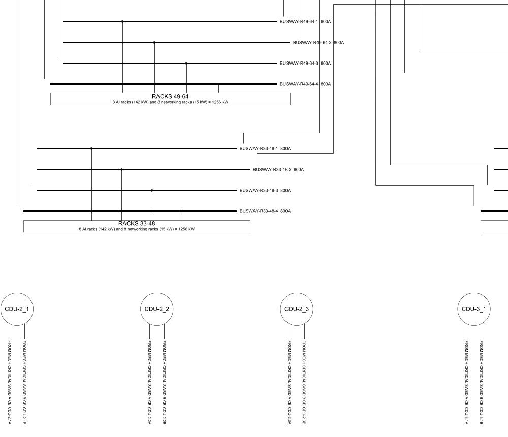
These drawings sit next to the pipe router in SD-DC, which already returns each routed pipe as an IndustroML connection. A routed pipe plus a placed P&ID is the start of design to drawing without a drafter redrawing it by hand.
A validator that catches what it claims to
Before any of this, the validator needed fixing. Its duplicate-id check ran on dicts keyed by id, which keep only the last of any repeat, so it could never fire. It now reads the lists as written:
for key, kind in (("containers", "container"), ("assets", "asset"),
                  ("interfaces", "interface"), ("connections", "connection")):
    seen: Set[str] = set()
    for x in model.get(key, []) or []:
        xid = x.get("id")
        if xid in seen:
            errs.append(f"Duplicate {kind} id: {xid}")
        seen.add(xid)
(validate_industroML.py L107–116)
It also checks each asset's kind against the domain the catalogue gives it, so a pump in the electrical domain is caught. Each check now has a test that breaks a model in exactly that way and expects the error.
The editor's 49 Jest tests now run in two seconds instead of seven minutes. The fix wasn't in the code. The repo lived in iCloud Drive under a path with spaces, which made git and Jest so slow the suite's output never came back. Moving it out was the fix.
What doesn't work yet
Automatic layout is reasonable, but no drafter. Cable text is placed beside its line without collision checks, and on a crowded P&ID a line number can still touch a line. The model has no port positions on equipment and no protection settings, so neither is drawn. Control loops stop at the instrument bubble, with no signal lines. The code is on GitHub, though it has no licence file yet.